Extruding Silhouettes for 3D Printing with Inkscape and OpenSCAD
Published on in 3D Printing
I recently found myself in a position where I wanted to extrude a logo so I could 3D print it. Unfortunately, this is a pretty difficult process to figure out without instructions. Therefore, I decided to document it. This process assumes you’re starting with a pixel-based image (bitmap, jpg, etc). If instead you have a vector graphic (SVG, etc) you should be able to do this by starting at the export step.
Software Used
- Inkscape 0.48.4-r9939 (latest through Debian testing as of time of writing)
- OpenSCAD 2013.06.09 (Also Debian-testing latest)
- A Debian-testing system (though this shouldn’t matter)
Process
As the highest level we need to accomplish three steps:
- Convert the pixel (bitmap) image to a vector graphic
- Export the vector graphic in a format OpenSCAD will use
- Extrude it in OpenSCAD
The last step is documented solely because there are a number of little details which can totally stop this process from working if you don’t get them exactly correct. Otherwise, its just a standard 2D to 3D extrusion.
Converting to Vector Graphics
Lets start with our example logo:

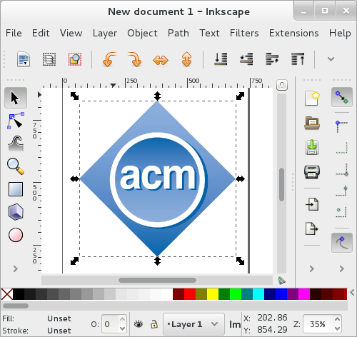
I’ve borrowed the ACM’s logo for this process.
First step: get it into inkscape. In my case, this is a simple copy-paste. It ends up looking like this:
Next, we need to convert this to a vector graphic. The best way to do this is to ask inkscape to trace it. Go to: Path -> Trace Bitmap. You’ll need to make sure the image is still selected. You’ll see something like this:
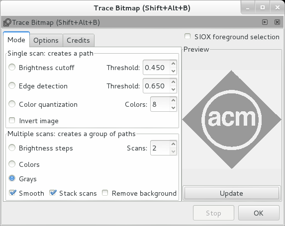
I use the following settings:
- Mode: Grays
- Scans: 2
- Remove background
Press update to make sure the graphic still looks acceptable to you, then OK to accept. Then close the trace window. Next, delete the original bitmap.
Now is a good time to make any edits to the vector graphic you want to make - for example, touching up lines that didn’t trace properly.
Exporting
In this step, we’ll be exporting the traced image to a DXF file, the format that OpenSCAD is capable of importing. Unfortunately, the DXF format is much, much more versatile than OpenSCAD’s parser. So we need to do a little tuning. (Some of these issues likely come from inkscape’s native format being SVG, which is more flexible and tolerant than DXF - SVG is a display format, DXF an engineering format).
Checking for Path Completeness
The first step to a successful export is checking the paths produced by inkscape are complete. Inkscape has a habit of not connecting the first and last points on a path if there is a straight line between them. When rendering visually, Inkscape knows to keep the fill color there, so the object looks correct, but actually has an empty path. However, if the path is all curves (like the circle around ACM in our sample) Inkscape will correctly connect the start and end points.
In order to check this, we need to change modes in inkscape to “Edit paths by nodes”. In order to do so, press F2 or click the highlighted button:
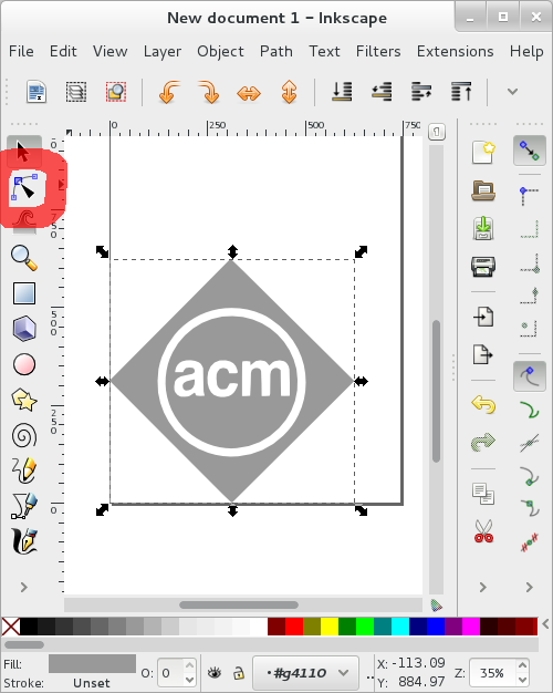
This will result in the screen looking like this:
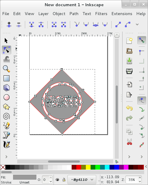
Let me highlight two parts of this in order to show what I mean by Inkscape leaving paths uncompleted. Note how, almost everywhere, paths are marked in red, except in the highlighted locations:

Note how you don’t see the red path in the two areas highlighted. In order to fix this, select the nodes on each end of the gap and press the “Join elected endnodes with a new segment” button. It’s the one in the upper left which looks like  .
.
Flatten Beziers
OpenSCAD doesn’t understand the concept of a spline. However, splines are rather integral to the the DXF file format. Therefore, if we want a DXF that OpenSCAD can understand, we need to get rid of the splines. To do so, go to “Extensions -> Modify Path -> Flatten Beziers…” This will pop up a box asking you how flat you want to make things. In general, I find 0.2 to be correct, depending on the complexity of the vector image. Smaller numbers are more true to the original image, but take more time to render. Graphics made mostly of circles are simpler, and can take larger numbers. For example, here is our logo rendered at flatness 10:
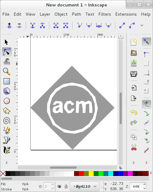
It looks a bit like an OpenSCAD circle on the default settings. While this looks passable, on more complex curves, this setting simply isn’t reasonable - parts of the paths cross, resulting in very odd-looking shapes. For this image, I’m going to go with flatness 1:
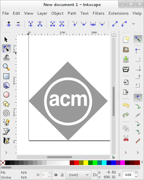
Feel free to use the live preview feature, but keep in mind it actually runs the whole algorithm and just shows it to you. If you’re playing with settings below 1, this could take a while. To apply your settings, click “apply” then close. DO NOT CLICK APPLY MORE THAN ONCE. Seriously. There is no progress indicator given by inkscape when it is working. So if your flattening takes a significant amount of time, clicking apply multiple times will result in multiple threads running to do the same work multiple times.
Alignment
The next step is to align your path so that you have some consistent understanding of its location between inkscape and OpenSCAD. if you were paying attention earlier, you might have noticed I moved the graphic to the lower-left hand of the page. Inkscape knows this as (0,0), as does OpenSCAD. By placing the graphic here, it will appear at (0,0) in the XY plane in OpenSCAD. Obviously this step can be done at any time - just make sure you do it before you export your graphic.
Saving
With the graphic all prepped, we need to save it. There are likely a multitude of settings that work, but I use this process. First, make sure the layer you want to export is selected - I’ve had files fail to export if no layer is selected. In inkscape, go to File -> Save…. Then select the “Desktop Cutting Plotter (AutoCAD DXF R14) (*.dxf)” file format in the lower-right of the save dialog. Name your file, save it wherever you’d like. When you press save, a dialog box will pop up asking you for settings. I use the following settings - I believe these are just the defaults.
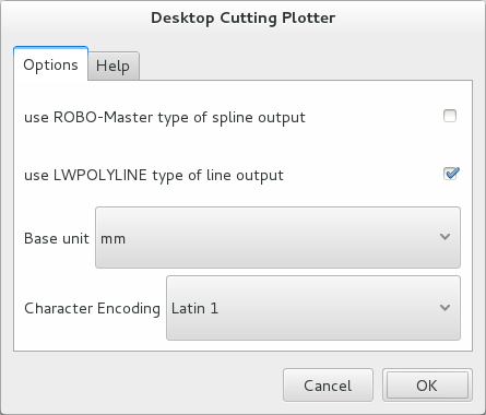
The most critical setting here is the base unit. OpenSCAD works in millimeters, so adjusting this to any other setting will result in weird imports.
OpenSCAD Extrusion
OpenSCAD has quite a few caveats when working with extrusion. We’ll be using the following script to do the extrusion:
First caveat: the filename given in the script (demo.dxf in this case), is relative to wherever the script is saved (if using the GUI). If you’re running OpenSCAD on the command line, I’m not sure how this works. My suspicion is that it is the same, but I have not not verified. This means that if you’re working with extrusions, you’ll need to save the script before it will run properly. (Alternatively, use absolute paths. However, that is an incredibly inflexible solution. To boot, OpenSCAD isn’t a stable enough piece of software that you should be working with unsaved work anyway. Naughty!). This script should then work. Running it will give you something like:

If your graphic doesn’t extrude, check that you’ve followed all the previous steps fully. The issue you’re most likely to come across is the incomplete paths. If you’re on a gnome system, opening them up in the gnome image viewer can often reveal where the path is incomplete.
As a final note: DXF is a 2D primitive in OpenSCAD, meaning that if you wish, you can work with it entirely in the 2D realm before moving it to 3D.
Conclusion
There you have it - a (mostly) simple process for turning vector images into 3D objects in OpenSCAD. Please let me know if you find additional pitfalls or things to be ware of in this process - I’ll add them to this post.